| Products Details | |||||||
|
|||||||
| Precision Electronically Compensated Current Transformer | ||||||||||||||||||||||||||||||||||||||||||||||||||||||||||||||||||||||||||||||
| Common Mode
Rejecter for testing meters with interconnected current and voltage
circuits The Common Mode Rejecter (CMR) is an electronically compensated uncoupling unit for elimination of interaction of simultaneously tested electricity meters having interconnected current and voltage circuits (closed I-P links). The CMR-I 1x30 is universal small-sized electronically controlled precision current transformer unit for galvanically isolating current. The through-hole, single wire unit with possibility of user defined current ratio is dedicated for testing of electricity meters with closed current and potential circuits. Versatility of the unit enables utilization in extensive applications as step-up or step-down precision current transducer with excellent dynamics. The CMR-I 1x30 is constructed as universally applicable
standalone unit with easy implementation to any existing test bench
system. The unit has negligible additional power loss therefore
no power increase is needed for closed link test capability. The
unit enables any user defined current ratio between primary and
secondary circuit. The current ratio is defined by primary and secondary
coil via number of respective turns. The internal electronics of
the device assures exact primary and secondary ampere-turns equality.
|
||||||||||||||||||||||||||||||||||||||||||||||||||||||||||||||||||||||||||||||
 |
 |
|||||||||||||||||||||||||||||||||||||||||||||||||||||||||||||||||||||||||||||
Precision Electronically
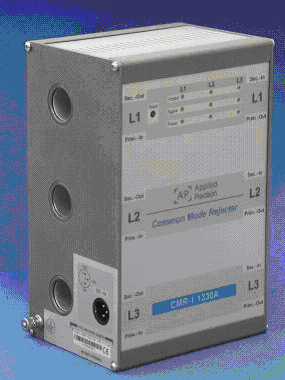
Compensated Current Transformer CMR-I 1330 |
CMR-I
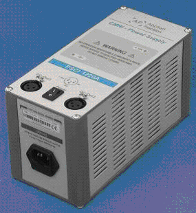
Power Supply PSCI 1220A |
|||||||||||||||||||||||||||||||||||||||||||||||||||||||||||||||||||||||||||||
 |
 |
|||||||||||||||||||||||||||||||||||||||||||||||||||||||||||||||||||||||||||||
CMR-I
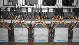
usage
|
Power
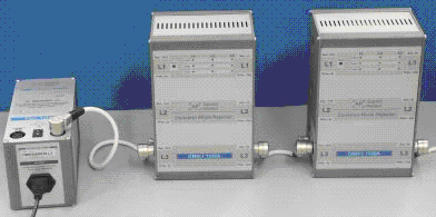
supply connections |
|||||||||||||||||||||||||||||||||||||||||||||||||||||||||||||||||||||||||||||